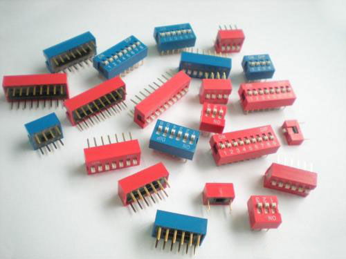
Talking about the working principle of the circuit of the DIP switch
2018-12-02

The DIP switch has four outputs and a common terminal in each digit dip switch. When the set decimal password is replaced by a binary number, all the bits containing 1 in it will be connected to the common terminal. All 0 bits will be left floating. In fact, the function of a switch will turn on all the bits and the common end.
The device for locking the door is also an electromagnet. The center of the electromagnet has a core. The position of the core is not exactly in the middle of the electromagnet. One end of the core is outside the electromagnet. When the electromagnet is energized, it will generate magnetism, and the magnet will attract the core. , the part of the iron core outside the electromagnet is moved toward the center of the electromagnet, and then the spring is placed against the other end of the electromagnet, so that the end of the iron core is moved from the outside of the electromagnet to the inside while the electromagnet is energized, and is broken. After the electric power, the iron core moves from the inside to the outside due to the action of the spring. This is like an ordinary lock. When the key is twisted, the lock bolt will be retracted, and the key will release the lock bolt and pop up. This achieves a method of replacing an ordinary lock with an electromagnet.
Knowing the principle of the dip switch and the lock, we can set up a circuit with a dip switch to control the circuit of the relay unlocking, that is, the electronic code lock control circuit of the dip switch, thereby realizing the function of the electronic lock. We can use all the 1 bits in the binary code converted by the gate to convert the decimal, and finally output a signal to control the turn-on and turn-off of the transistor to control the on and off of the electromagnet. When the input password (the converted binary password) contains one number equal to the number of one set in the circuit, the unlock function can be realized, so that some simple passwords can be implemented, but there is still a problem of heavy code. Careful analysis of 0--9 binary numbers will reveal that some values have the same position in 1 but only unequal. For example, the 1 position of the middle two digits of 6 (0110) and 7 (0111) is equal to just 7 more than one, if the password Set to 1, then when you enter the password 7, you can also achieve the function of 6, the same can open the door, and the password with 0 can not be set. This needs to be improved. We can add a NOR gate to the circuit. If the input is 0, the output will be 1 when the input is 0. When the 0 is all 0, the problem of re-code can be solved. Password problem. Use the NOR gate and the NOR gate to close the gate, and then use the output signal to control the triode. By connecting all the signals to the AND gate, and the floating signal is connected to the NOR gate, a perfect circuit can be set up, so that there is no problem such as re-code.
On the basis of these, there is still the problem of others trying to password. If someone else can continue to try the password and can still open the door, then a circuit is needed to prevent the password. After the analysis, it is decided to use the alarm to prevent the infinite trial password, that is, after inputting the password error three or three times 7 or more, an alarm sound is emitted, a shift register (74LS164) is used in the circuit, and the password register is recorded once the wrong password register is input. Each time the register is registered, it will output a high level on the corresponding pin. When the record is three times, the third pin will output a high level to control the generating circuit to generate an alarm sound. The alarm can be released when the correct password is entered again. This can effectively avoid the problem of trying passwords.


